How does sound move? Wave Propagation and Huygens’ Principle
The behavior of sound waves as they travel through a medium or reflect from an object can be found using a remarkably simple geometrical procedure, Huygens' Principle. This principle describes how wave fronts move.
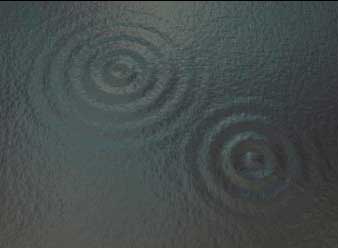
Photo courtesy of Robert Simmon, NASA GSFC
A wave front is a surface consisting of all points on a wave at the same position in a wave cycle. For example, all of the points located on the crest of the same wave form a wave front. Similarly, all of the points located at the trough of the same wave form a wave front. A series of waves can be represented schematically by a series of wave fronts. For example, one can draw the wave fronts corresponding to the crests of each of the succeeding waves. These wave fronts are then exactly one wavelength apart. (One could equally well draw the wave fronts corresponding to the troughs of each of the waves.)
Devised by the Dutch scientist Christiaan Huygens in 1678, Huygens' principle states that each point on an advancing wave front may be considered to be a new point source generating spherical Huygens' wavelets. If one knows the location of a wave front at one time, one can determine the location of the wave front at a slightly later time by drawing spherical arcs centered at points along the wave front. Each spherical arc is a Huygens' wavelet. The radius of each arc is given by the distance that sound travels in that small amount of time. As shown in the figure below, the initial wave front is labeled " t ". If the sound speed is c (meters/second), then in a small time increment, Δt (seconds), sound travels a distance cΔt (meters). The new wave front, labeled "t + Δt" is simply the envelope of these wavelets of radius c Δt, constructed by drawing the line tangent to the leading edges of the wavelets.
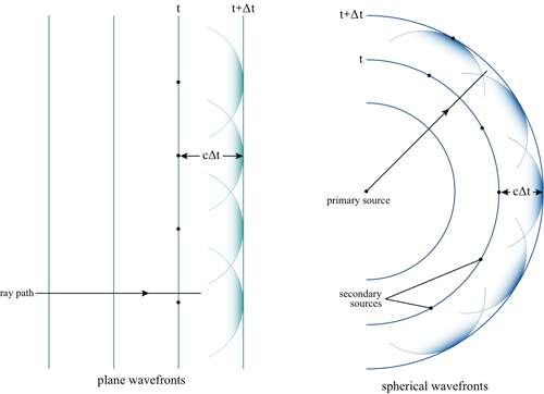
Plane wave fronts and spherical wave fronts.
Huygens' principle shows that plane wave fronts remain plane wave fronts as they travel, as each of the spherical wavelets for all of the points on each wave front have the same radius cΔt, and the envelope of the wavelets is therefore another plane wave. Similarly, spherical wave fronts traveling away from a point source remain spherical wave fronts. One implication of Huygens' principle is that the direction in which the wave fronts travel is locally perpendicular to the wave fronts, as shown in the figure above with the arrows. The local perpendicular therefore gives the direction in which sound rays travel.
Huygens' principle requires that one draw the envelope of the wavelets along the leading, rather than the trailing, edge of the wavelets. In order to apply Huygens' principle, one must therefore know the direction in which the wave front is traveling.
Huygens' principle can be used to help us understand why the angle of incidence is equal to the angle of reflection when sound reflects from a hard surface. The following figure shows what happens to plane waves traveling toward a reflecting boundary between two media.
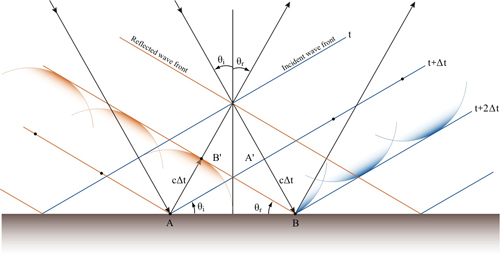
Consider an incident wave front that reaches point A on the boundary at time t. A short time Δt later, the Huygens' wavelet originating at point A' will have advanced forward a distance cΔt, reaching point B on the boundary. During that same short time period, the Huygens' wavelet originating at point A will also have traveled a distance cΔt, but in this case it has to travel away from the reflecting boundary. The reflected wave front is tangent to the wavelet originating at point A and passes through points B and B´.
From the geometry, one can show that the angle θi between the incident wave front and the boundary (angle of incidence) equals the angle θr between the reflected wave front and the boundary (angle of reflection). Using the definition of the trigonometric sine function and letting A´B, AB´, and AB stand for the lengths of the line segments between the points A, A´, B, and B´:
$latex \textup\theta_ = \frac &s=3$
$latex \textup\theta_ = \frac &s=3$
From Huygens' principle, the two line segments A´B and AB´ both have length cΔt. Therefore,
$latex \textup\theta_ = \frac = \textup\theta_ &s=3$
and,
$latex \theta_ = \theta_ &s=3$
Huygens' principle gives the result that the angle of incidence is equal to the angle of reflection.
Huygens' principle can also be used to help us understand the refraction of sound. It can be used to derive Snell's Law, which relates the angle of incidence to the angle of refraction when sound travels from one medium into another with a different sound speed. The following figure shows what happens to plane waves traveling toward the boundary between two media with different sound speeds. Some of the sound will be reflected, as above, but some will transmitted through the boundary. For simplicity, in this figure only the energy transmitted through the boundary is shown.
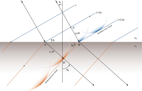
Refraction
Consider an incident wave front that reaches point A on the boundary at time t. A short time Δt later, the Huygens' wavelet originating at point A´ will have advanced forward a distance c0Δt, where c0 is the sound speed in the first medium, reaching point B on the boundary. During that same short time period, the Huygens' wavelet originating at point A will have traveled a distance c1Δt into the second medium, where c1 is the sound speed in the second medium. The transmitted wave front is tangent to the wavelet originating at point A and passes through points B and B´.
Again using the definition of the trigonometric sine function,
$latex \textup\theta_ = \frac &s=3$
$latex \textup\theta_ = \frac &s=3$
From Huygens' principle, the line segment A´B has length c0Δt, while line segment AB´ has length c1Δt , giving
$latex \textup\theta_ = \frac &s=3$
$latex \textup\theta_ = \frac &s=3$
Therefore,
$latex \frac{\textup\theta_} = \frac = \frac{\textup\theta_} &s=3$
and,
$latex \frac{\textup\theta_} = \frac{\textup\theta_} &s=3$
This result is Snell's Law, relating the angle of incidence to the angle of refraction.
The figure is drawn assuming that c1 is greater than c0 . This case is applicable to the reflection and refraction of sound waves at the seafloor, which typically has a higher sound speed than seawater.